ANALYSIS OF MISALIGNMENT BETWEEN OPTICAL AND MOTION AXIS FOR FOCUS STACKING.
- Apr 20, 2018
- 3 min read
I have been asked many times about why there are streaking patterns around border of final stacked image. Well, the most common cause of these streaking patterns is due to the optical instruments used — the magnification of optical instrument changes when the distance between the subject and sensor changes. When stacking algorithm attempts to align all images, there will be mismatch of subject size. Information in one image just does not exist in another, thus stacking software often fills the final image with some arbitrary (arbitrarily chosen) pixels. However, if a telecentric optical instrument is used, due to the nature of telecentricity, there is no change in magnification, therefore there should be no or very little streaking patterns. But many still get streaking patterns even when a telecentric optical instrument is used. What gives? Here is why!

The above image is stacked using a telecentric objective, a Mitutoyo QV 2.5X 0.14, however, it still exhibits streaking pattern on the left hand side (as highlighted in red). What is causing this, in particular only the left hand side, is the misalignment of optical and motion axes — as stacking progress along, even though the objective is telecentric, the position of the subject changes due to the misalignment, therefore, information in one image simply does not exist in subsequent images, and stacking software will simply fills the missed pixels with some arbitrarily decided pixels.
This aspect of focus stacking is very often ignored or neglected, particularly when a non-telecentric optical instrument is used because it is often blamed on the optical instrument.
I have not found any practical way to detect and correct this kind of misalignment, but the following analysis might be of a guide once a stack is done.
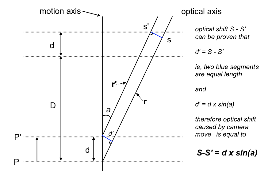
In above figure, the misalignment is exaggerated to illustrate the point. Here, stacking process starts at position P and moves to position P’ over a distance of d. The misalignment between optical axis and motion axis forms an angle a. The two blue segments d’ in the figure is the optical shift due stacking distance of d. It can be proven that the two blue segments are equal using basic geometry principles.
So from the figure above we can conclude that d’ = d * sine(a). For most of us, our intention is to minimize the angle a, ie, we can eyeballing the camera setup and where the lens/objective is pointing, and intuitively, we do tend to minimize the angle. Therefore the angle a is very often very, very small. There is a mathematical approximating of sine(a), which is a = sine(a) when a is very small and measured in radians. So this means:
d’ = d * a
So what good is this analysis? Well, it provide an estimate about how much misalignment is and it can be used to correct the misalignment. How? Well the shift in optical axis, the d’, can be measured by the width of streaking pattern in the same dimension.
Here is how to calculate the estimate. Let W be the sensor width in millimeters and w be the horizontal count of pixels. This means, the pixel width w’ is:
w’ = W / w
so, if we count number of pixels for the streaking pattern, label it as c, and multiply it by w’, we get the physical shift on the sensor, label it as ds. So, we have
ds = w’ * c ==> ds = c * W / w
where W is sensor width, w is pixel count across frame
But the actual physical shift d’ is ds times magnification M, so we have:
d’ = M * c * W / w
and from the formula d’ = d * a, with d (stacking distance) known, we can calculate the angle a
a = M * c * W / w / d
So, we can estimate how much correction to be applied to your setup and this is the conclusion of this blog.


Comments